WASH-WATER + DEMULSIFIER DOSING
Water ratio, injection location, and demulsifier dosage are selected from crude salt, water, and emulsion behavior.
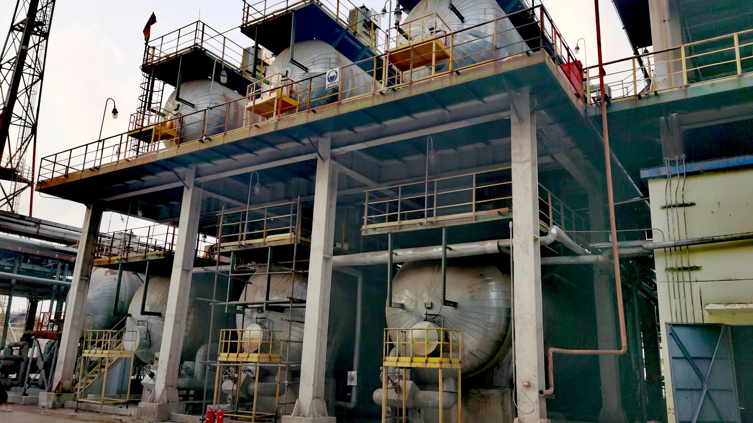
PROCESS
01 / SYSTEM SCOPE
Water ratio, injection location, and demulsifier dosage are selected from crude salt, water, and emulsion behavior.
A static mixer or mixing valve creates the required dispersion so salts enter the water phase without excessive emulsification.
Fine water droplets polarize, collide, and grow in the electric field before settling by density difference.
Temperature, pressure, current, and interface are monitored while separated brine is routed to recycle or downstream treatment.
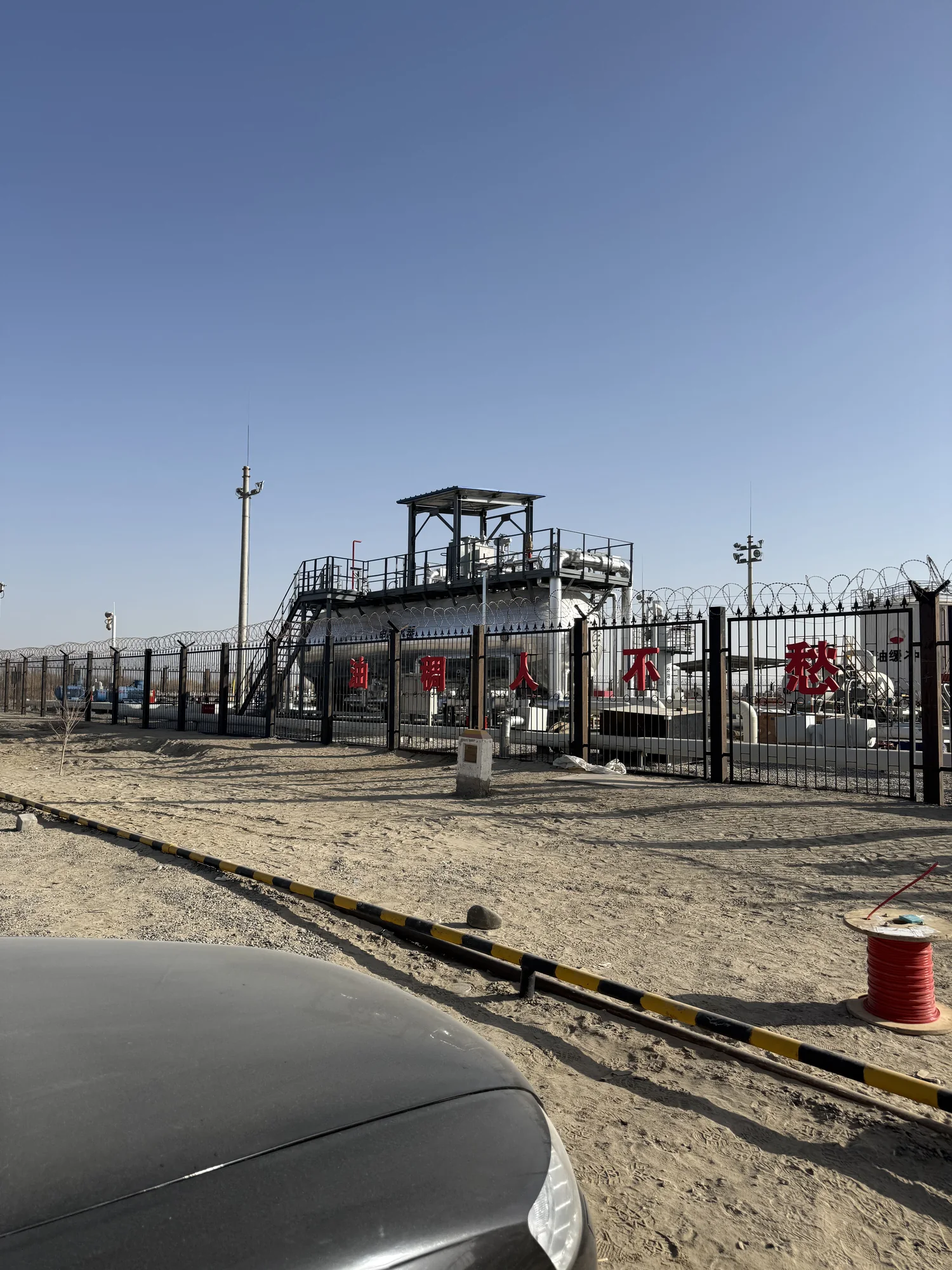
02 / PROCESS CHAIN
Crude is heated into a suitable treatment window and contacted with wash water and, where required, demulsifier. Mixing disperses the water phase and transfers salts before the stream enters the desalter, where electric-field and gravity forces complete the separation.
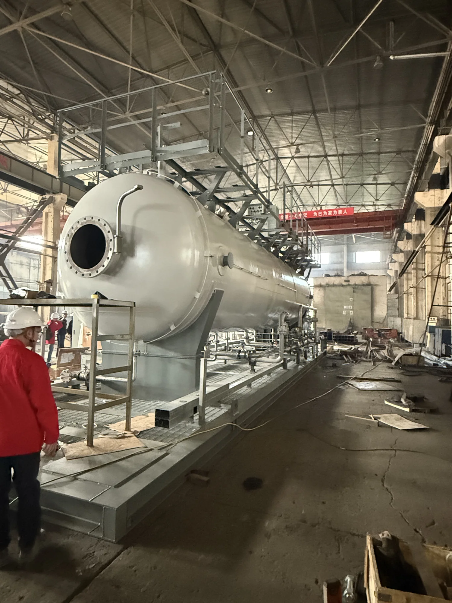
03 / VESSEL INTERNALS
The vessel can be understood as a water zone, emulsion and weak-field zone, strong-field coalescence zone, and clean-oil zone. Inlet distributors, electrodes, clean-oil collectors, and bottom drainage maintain the flow field and provide space for droplet growth and settling.
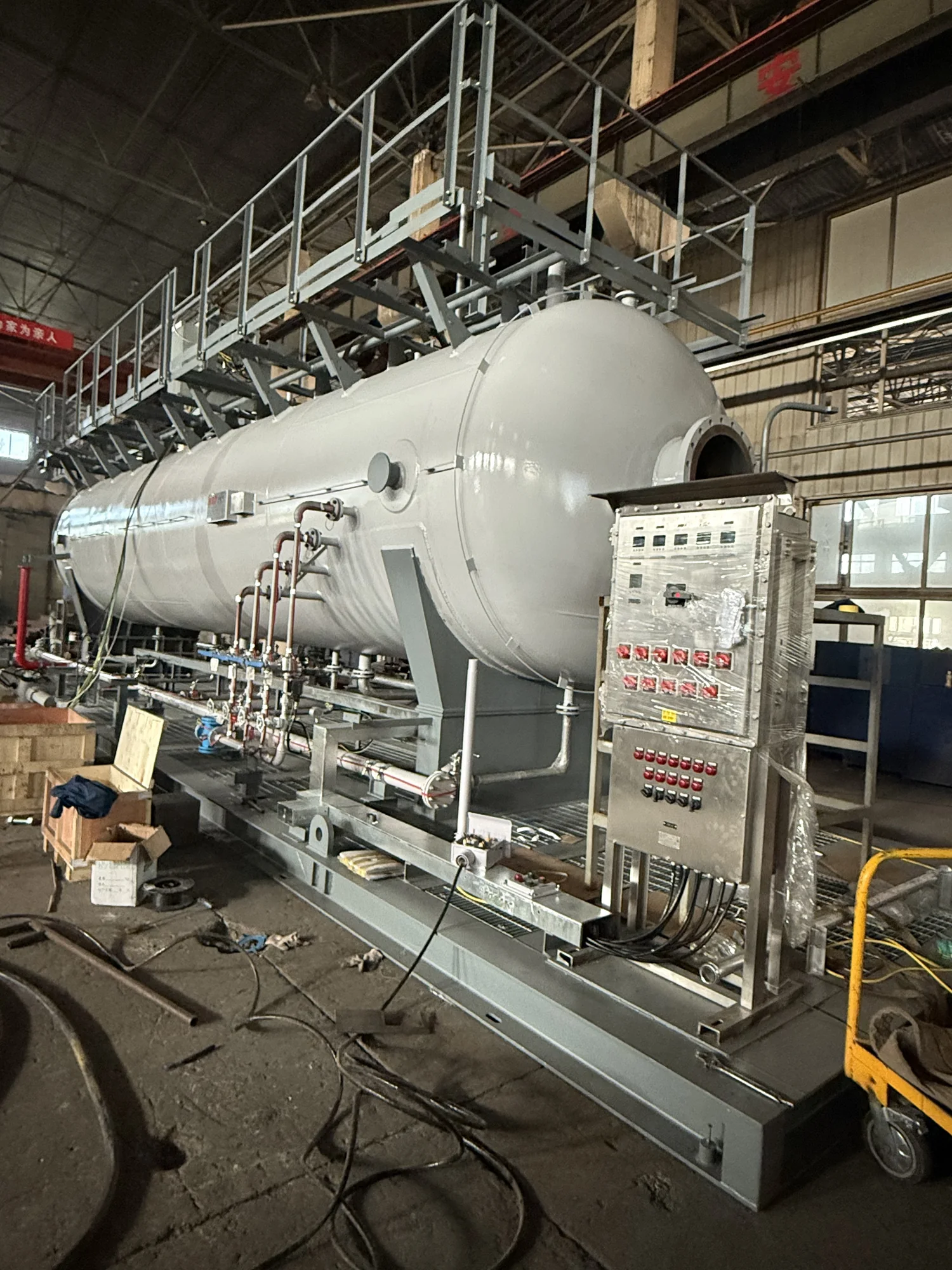
04 / POWER + CONTROL
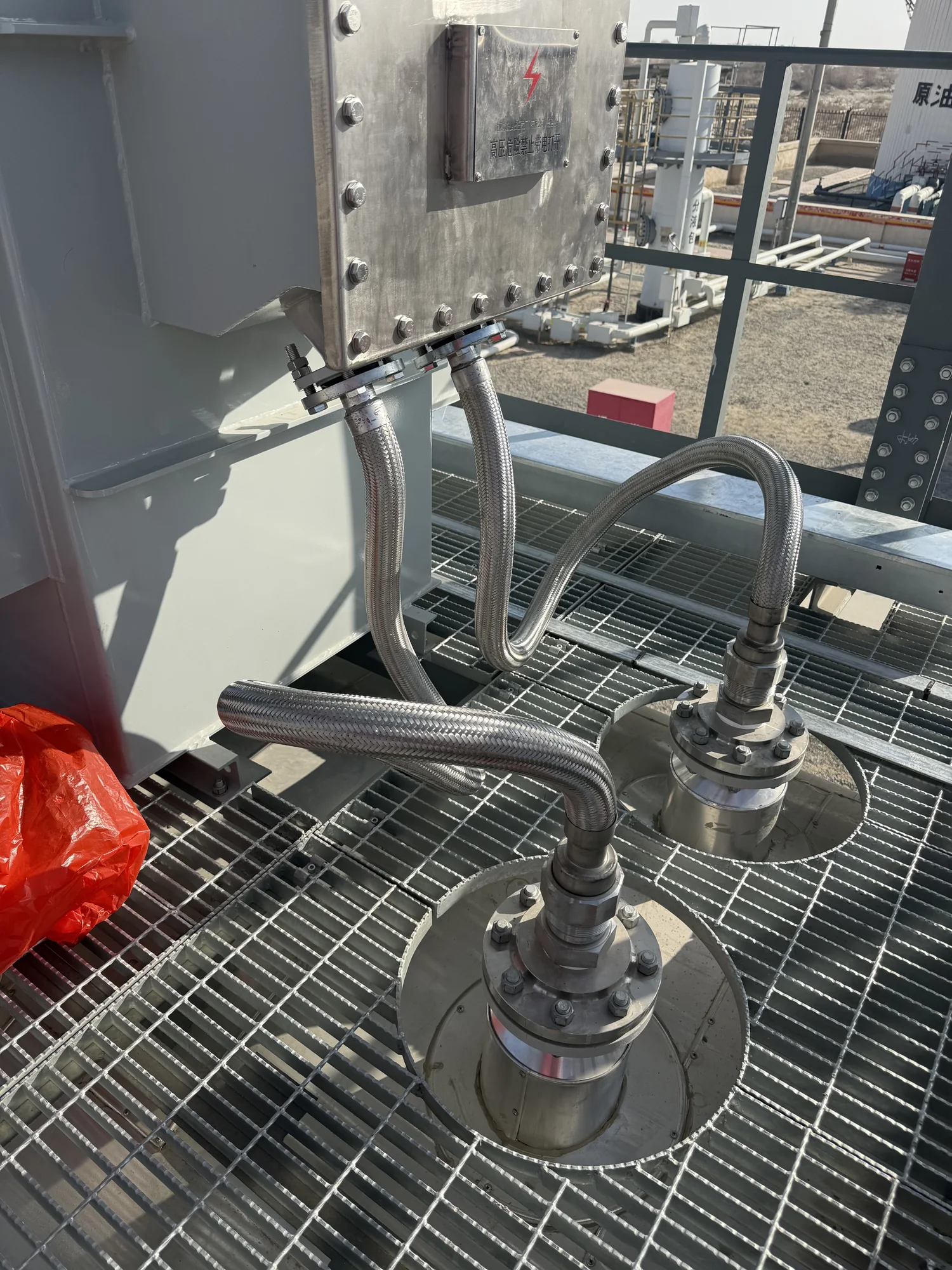
The electrical system combines power, regulation and protection, electrodes, and high-voltage feedthroughs. Process controls cover flow, temperature, pressure, interface, voltage, and current, with logic intended to stabilize separation and protect the package.
05 / PROJECT INPUTS
Selection requires crude properties, throughput, inlet and outlet salt and water targets, pressure and temperature range, wash-water quality, available power, plot constraints, and control boundaries. During operation, trends help distinguish a mixing and mass-transfer problem from an electric-field, interface, or drainage problem.